

 Korean
  English
  Arabic
  German
  French
  Spanish
  Turkish
  Italian
  Russian
  Persian
  Bengali
  Hebrew
  Persian (Afghanistan)
  Scottish Gaelic
  Panjabi
  Croatian
  Slovenian
  Greek
Greek  Afrikaans
  Czech
Czech  Japanese
  Portuguese













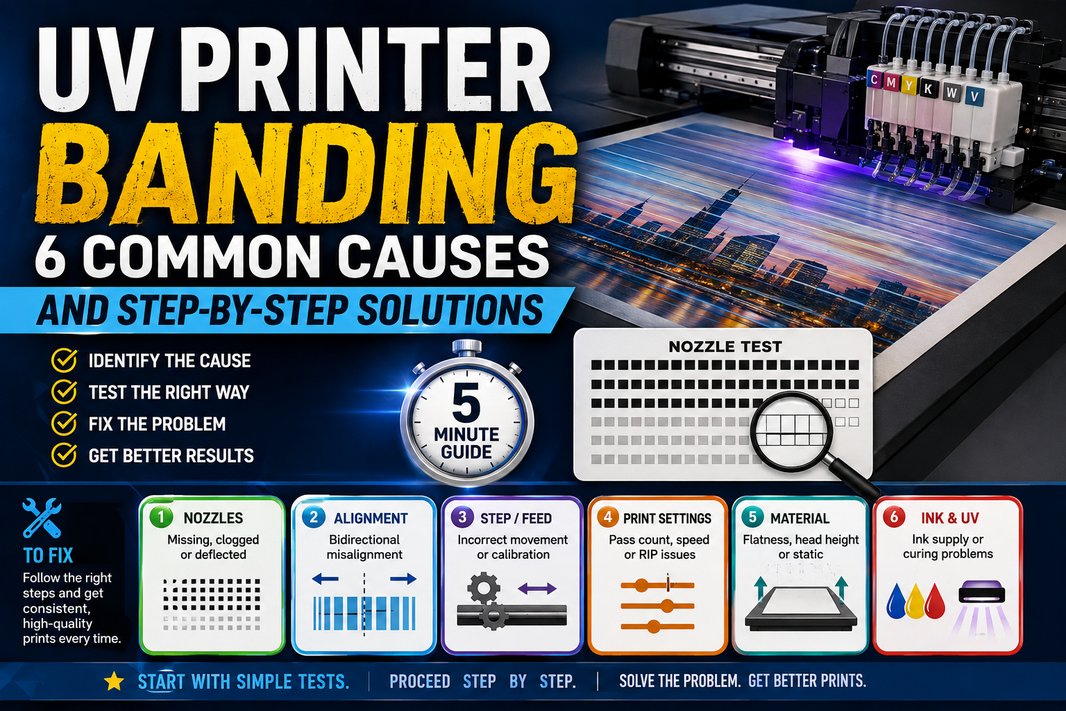
UV Printer Banding: 6 Common Causes and Step-by-Step Solutions
UV printer banding can appear as horizontal light lines, dark overlapping bands, repeated color stripes, doubled edges, grainy gradients or uneven white ink and varnish layers. Although many operators immediately assume that the printhead is clogged, missing nozzles are only one possible cause.
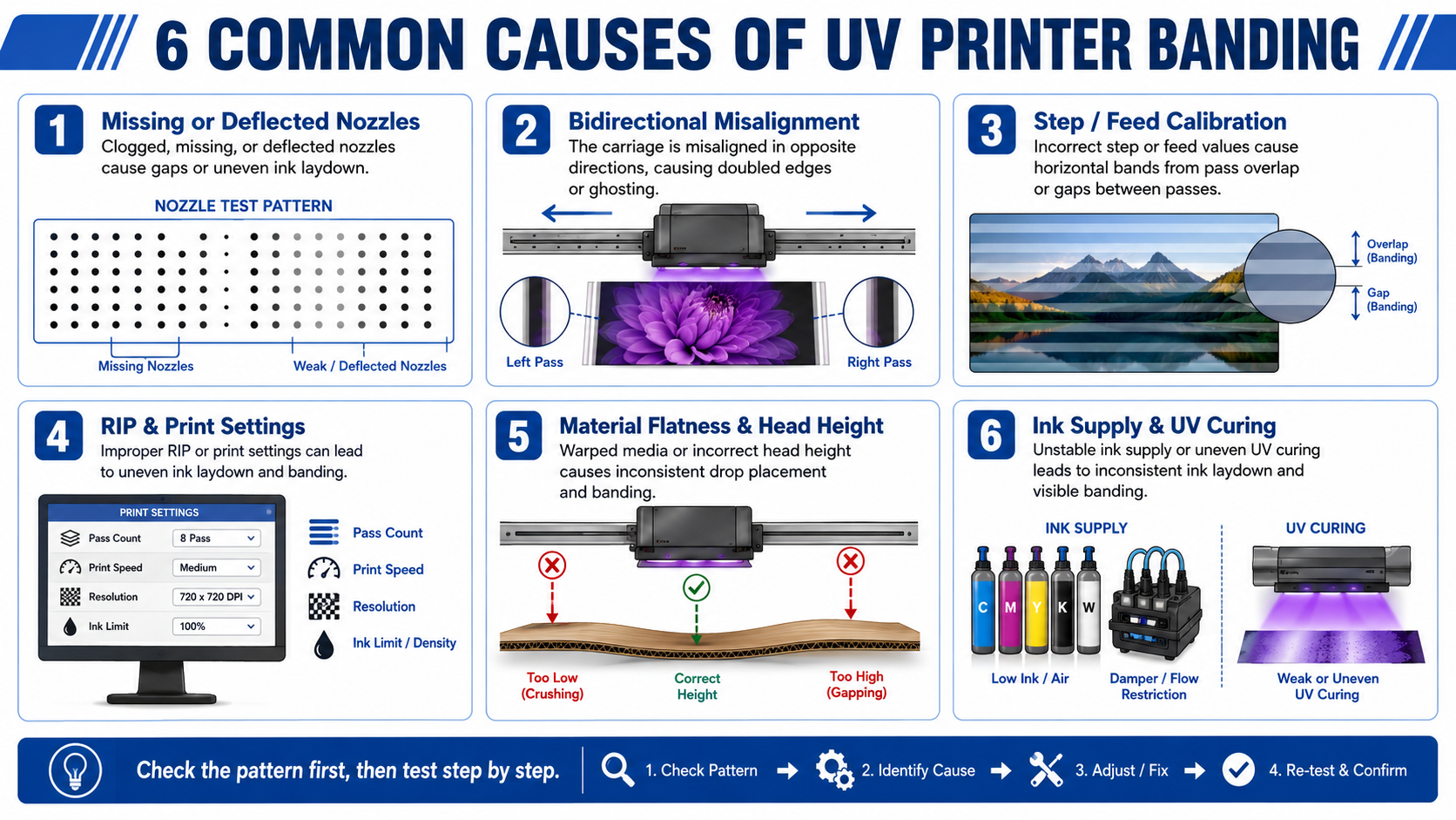
Banding can also result from incorrect bidirectional calibration, inaccurate platform stepping, unsuitable RIP settings, low pass counts, warped materials, excessive printhead height, unstable ink supply or uneven UV curing.
The most effective troubleshooting method is to observe the direction, spacing, color and operating conditions of the lines before changing any settings. This guide explains six common causes and provides a step-by-step process that moves from the fastest test to the more complex mechanical and technical checks.
Important: Change only one variable at a time. If you change the pass count, print direction, calibration, ink settings and head height together, you will not know which adjustment improved or worsened the result.
Quick Diagnosis: What Does the Banding Pattern Tell You?
The appearance of the lines often reveals which part of the printing process should be checked first. Use the following table as an initial guide.
| Banding Pattern | Likely Problem Area | Best First Test |
|---|---|---|
| Random lines or missing areas in one color | Missing, clogged or deflected nozzles | Print a nozzle test |
| Doubled vertical edges or small-text shadows | Bidirectional alignment | Print the same file in unidirectional mode |
| Regular light or dark bands across the full print | Step or media-feed calibration | Print a step-adjustment pattern |
| Lines improve when the pass count is increased | Print mode, nozzle overlap or step accuracy | Compare two pass modes |
| Only white ink has stripes | White nozzles, circulation or ink supply | Print a white-only nozzle and density test |
| Only varnish has visible gloss bands | Varnish nozzles, ink limit or UV curing | Print a varnish-only test |
| Lines appear only on one material | Flatness, head height, static or coating | Test on a standard flat material |
| Lines appear near the platform edge | Vacuum, platform level or material height | Check adsorption and flatness |
This table identifies the most likely inspection area, not a final diagnosis. Two different faults can sometimes create a similar visual result.
Identify the Banding Pattern Before Cleaning
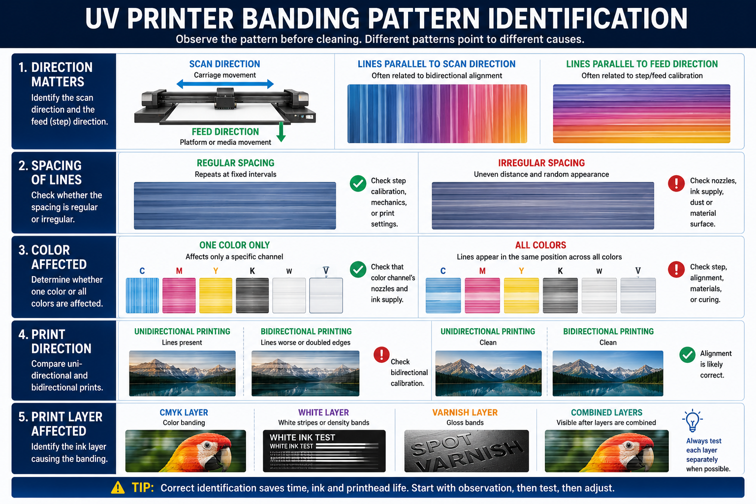
Before performing any cleaning, mark the direction in which the print carriage moves and the direction in which the platform or material advances. Do not rely only on the words “horizontal” and “vertical,” because those descriptions can change when the artwork or material is rotated.
Scan Direction Versus Feed Direction
그만큼 scan direction is the direction in which the print carriage moves across the material. The feed or step direction is the direction in which the platform or media advances between printing passes.
Lines related to bidirectional alignment usually follow the scan behavior. Lines related to platform stepping or media feed often appear at the boundaries between adjacent printing passes.
Regular Versus Irregular Spacing
Regularly spaced bands suggest a repeating process. Possible causes include step calibration, carriage movement, pass overlap, encoder signals or mechanical cycles.
Irregular lines are more likely to be associated with random nozzle loss, unstable ink supply, dust, material contamination or local surface differences.
One Color Versus All Colors
If banding appears in only cyan, magenta, yellow, black, white or varnish, first check the nozzle condition and ink supply for that specific channel.
If all colors show a line in the same position, the problem is more likely to involve movement, feed, material flatness, RIP settings or curing rather than one individual printhead channel.
Unidirectional Versus Bidirectional Printing
Bidirectional printing places ink while the carriage moves in both directions. It increases speed but requires accurate drop-position calibration.
If the print is clean in unidirectional mode but shows doubled edges, color shifts or fine lines in bidirectional mode, perform bidirectional calibration before cleaning the printhead repeatedly.
CMYK Versus White Ink and Varnish
Examine the layers separately whenever possible. A CMYK image can look striped even when the actual problem is an uneven white layer beneath it. Varnish may also create visible gloss bands without a significant difference in printed color density.
Cause 1 — Missing, Clogged or Deflected Nozzles
Missing nozzles are one of the most common causes of UV printer horizontal lines, especially when the lines appear in one color or in irregular positions.
Print and Read the Nozzle Test
Print the complete nozzle-test pattern for CMYK, white ink and varnish. Use a material that makes every channel easy to see. Place dark material beneath a transparent white-ink test when necessary.
Look for the following patterns:
- A few random nozzles are missing: mild blockage or contamination may be present.
- A continuous nozzle group is missing: the damper, ink line, filter or printhead channel may be restricted.
- One complete channel is missing: check the ink supply, cable, control signal and printhead channel.
- Dots are present but deflected: ink may be leaving the nozzle at an incorrect angle, causing mist, graininess or fine lines.
Use the Correct Cleaning Sequence
- Print and photograph the first nozzle test.
- Perform one normal cleaning cycle for the affected channel.
- Allow the pressure and ink supply to stabilize.
- Print a second nozzle test.
- Compare the two tests.
If the test improves, confirm that it remains stable before production. If there is no improvement, do not perform unlimited heavy cleaning. Repeated cleaning consumes ink and may not solve a blocked damper, air leak, cable issue or damaged channel.
For safer printhead maintenance, read our guide on how to extend Ricoh and Epson printhead life.
When the Nozzle Test Is Good but Banding Remains
A complete nozzle test does not rule out bidirectional misalignment, step errors, unsuitable pass settings, warped material or uneven curing. Continue to the next test instead of assuming the printhead is the cause.
Cause 2 — Incorrect Bidirectional or Printhead Alignment
Bidirectional misalignment occurs when ink printed during left-to-right carriage movement does not land in exactly the same position as ink printed during right-to-left movement.
The result may look like:
- Doubled edges around small text.
- Color shadows along vertical lines.
- Thin repeated bands in detailed images.
- Reduced sharpness in barcodes and fine graphics.
- Color shifts between adjacent carriage passes.
Test the Same File in Unidirectional Mode
Use the same artwork, material, resolution, pass count, ink configuration and head height. Change only the print direction from bidirectional to unidirectional.
- If the lines disappear, bidirectional alignment is the most likely cause.
- If the lines remain unchanged, continue checking nozzles, step accuracy, materials and ink supply.
- If small text becomes noticeably sharper, the bidirectional value probably requires adjustment.
Calibrate for the Actual Material Height
Drop-position accuracy changes when the distance between the printhead and material changes. A calibration completed on a thin sheet may not produce the same result on a thick box, board or jig.
Perform bidirectional calibration using the actual production head height whenever practical. Verify the adjustment by printing small black text, thin vertical lines and a high-contrast alignment pattern.
Cause 3 — Incorrect Step, Feed or Motion Calibration
On a UV flatbed printer, the platform or gantry must advance by a precise distance between passes. On a roll-to-roll printer, the material-feed system must move the media accurately.
Recognize Step-Related Banding
Step or feed problems often create:
- Regular bands across the full width of the image.
- Lines with similar spacing from beginning to end.
- Light gaps between adjacent passes.
- Dark lines caused by excessive pass overlap.
- Banding that affects all colors in the same location.
Light Gaps Versus Dark Overlap
A light line may indicate that the platform or material advances too far, leaving insufficient overlap between passes. A dark line may indicate that the advance distance is too short, causing one pass to overlap the previous pass excessively.
Use the printer’s official step or feed calibration pattern. Avoid changing values by large amounts based only on visual guessing. Make small adjustments and print a new comparison pattern after each change.
Check Motion Components
If the correct adjustment value changes repeatedly or cannot produce a stable result, inspect the motion system for:
- Encoder strip or encoder sensor contamination.
- Loose or damaged drive belts.
- Abnormal guide-rail resistance.
- Screw, motor or platform movement errors.
- Mechanical backlash.
- Roll-media tension or feed resistance.
Fixed repeating marks at the same distance may indicate a mechanical or encoder-related cycle rather than nozzle blockage.
Cause 4 — Incorrect RIP, Pass or Print Settings
Print settings affect how individual nozzle rows and passes overlap. A machine may produce acceptable quality in one mode but visible banding in another.
The Pass Count Is Too Low
A lower pass count increases production speed, but each pass covers a larger part of the final image. Missing nozzles, step errors and drop-placement differences therefore become more visible.
Large solid colors, smooth gradients, dark backgrounds and high-opacity white layers usually reveal low-pass banding more easily than photographs with complex detail.
Compare Production Mode and Quality Mode
Print a small section of the same file using:
- The current production mode.
- One higher pass level.
- Unidirectional mode.
- The manufacturer’s recommended quality mode.
If banding improves at a higher pass count, the extra interlacing may be compensating for missing nozzles, step overlap or unstable ink delivery. This is useful diagnostic information, but it does not always mean the underlying problem has been repaired.
Check Resolution, Profile and Ink Limit
Confirm that the RIP resolution and waveform or print mode match the printer configuration. Also verify:
- The correct ICC profile is selected.
- The material profile is suitable for the current substrate.
- CMYK ink limits are not excessively low or high.
- White ink and varnish layer settings are correct.
- The selected printhead channel configuration matches the machine.
- Production and quality modes are not using different unsupported settings.
Cause 5 — Material Flatness, Head Height and Static Electricity
A perfect nozzle test cannot compensate for an uneven material surface. UV flatbed printing depends on maintaining a controlled distance between the nozzle plate and the substrate.
Check Material Flatness
Inspect the material for:
- Warped centers or raised corners.
- Uneven thickness.
- Weak vacuum adsorption.
- Dust or objects beneath the material.
- Poorly supported products inside a jig.
- Movement caused by insufficient fixing.
If the distance changes across the print, ink dots may become larger, less accurate or more affected by airflow. The result may appear as blurred sections, grainy bands or repeated density changes.
Avoid Excessive Printhead Height
Raising the printhead too far reduces the risk of a head strike, but it also increases ink-droplet travel distance. This can reduce edge sharpness and increase ink mist.
Use the lowest safe head height for the actual material. Never lower the head without confirming that the full product surface, fixtures and raised edges are clear.
Check Static Electricity
Plastic sheets, acrylic, PVC and other materials may hold static electricity, especially in dry environments. Static can attract or deflect fine ink droplets, creating mist, rough gradients and irregular lines.
Use an approved static-removal device, maintain suitable humidity and clean the material surface before printing.
Test on a Standard Flat Material
Print the same file on a known flat and stable test sheet. If the banding disappears, focus on material flatness, surface treatment, static electricity, head height and vacuum adsorption rather than the printhead.
Cause 6 — Ink Supply, UV Curing or Environmental Conditions
Unstable Ink Supply
Air bubbles, partially blocked dampers, restricted filters and unstable negative pressure can reduce the amount of ink reaching the printhead during production.
This may create:
- Banding that becomes worse during long jobs.
- Lines that disappear after cleaning and return later.
- One color becoming weaker than the others.
- White ink density changing during the same print.
- Nozzle loss at high printing speed.
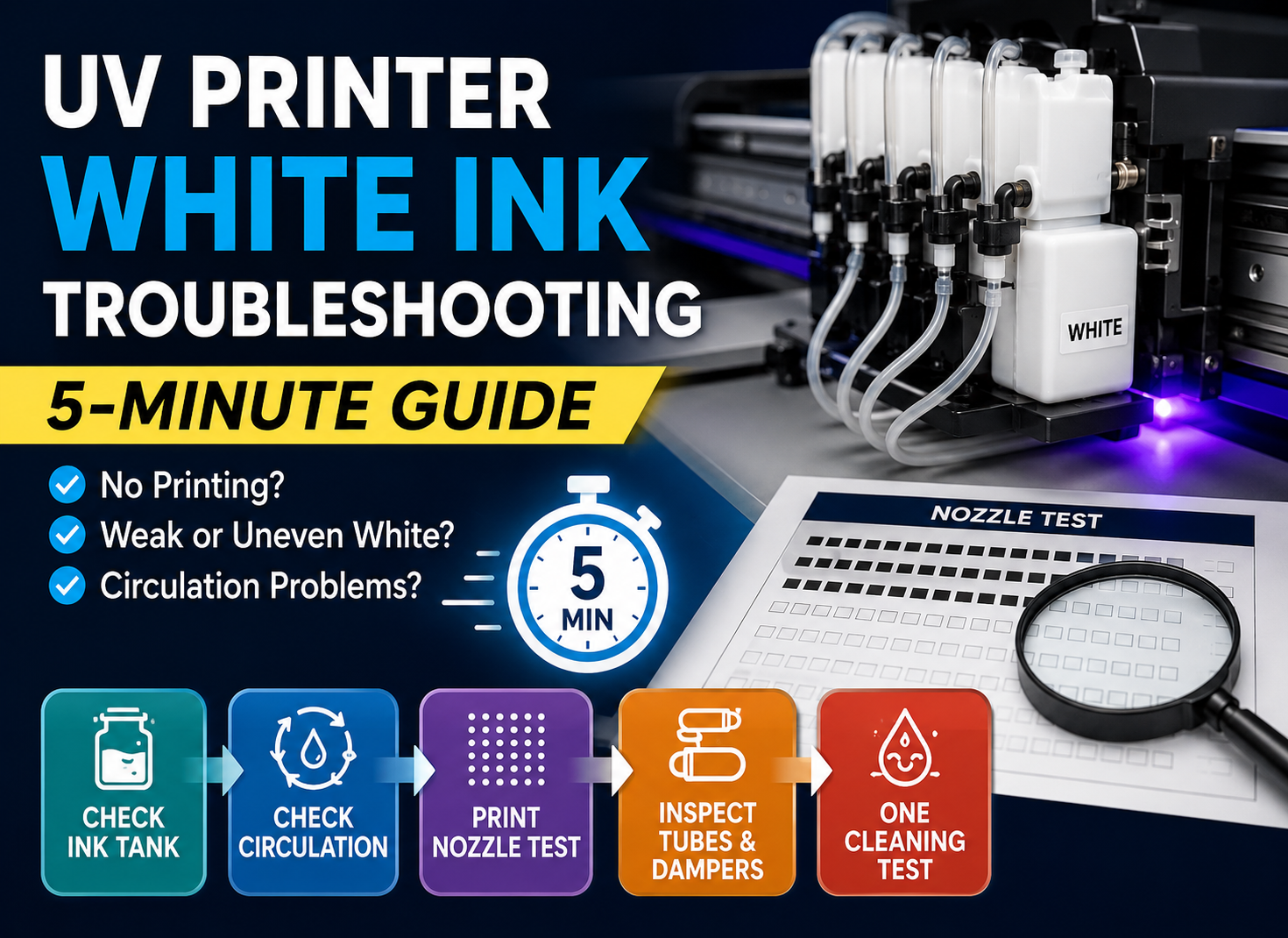
For white-channel problems, follow our UV printer white ink troubleshooting guide before removing any tubes or dampers.
White Ink Sedimentation
White pigment can settle when agitation and circulation are insufficient. As the pigment concentration changes, the white underbase may produce visible density bands even when the CMYK layer appears normal.
Check the white ink tank, agitator, circulation flow, return line and white nozzle test. Do not mix incompatible ink brands or add unapproved thinner to the tank.
Uneven UV Curing
UV lamp intensity, lamp distance, carriage speed and curing settings affect the appearance of the cured ink surface. Uneven curing may create:
- Gloss differences.
- Visible varnish stripes.
- Alternating matte and glossy sections.
- Surface-texture differences.
- Apparent dark or light bands even when ink density is similar.
A curing band may look like a color band. View the print under different lighting angles to determine whether the difference is mainly color density or surface gloss.
Temperature, Airflow and Dust
Large temperature changes can affect ink viscosity and flow. Strong airflow from fans or air-conditioning outlets can influence ink mist and material temperature. Dust can contaminate the nozzle plate or create local defects on the substrate.
Keep the printer environment stable and avoid directing strong airflow across the printing area.
Step-by-Step UV Printer Banding Troubleshooting Sequence
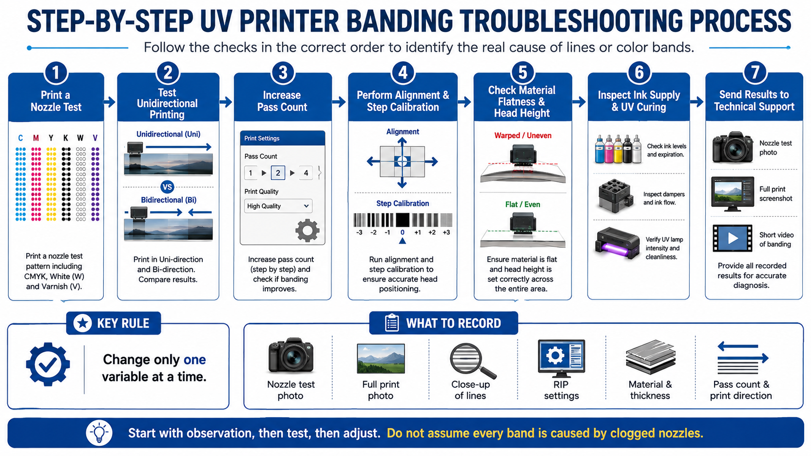
Use the following sequence to avoid unnecessary cleaning, part replacement and parameter changes.
Step 1 — Print a Complete Nozzle Test
Check CMYK, white ink and varnish. Photograph the full pattern and record any missing or deflected nozzles.
If the nozzle test is incomplete, perform one controlled cleaning and print a second test. If the test remains unchanged, investigate ink supply or technical causes before continuing heavy cleaning.
Step 2 — Print the Same File in Unidirectional Mode
Keep every other setting unchanged. If the banding or doubled edges disappear, perform bidirectional calibration using the current material height.
Step 3 — Increase the Pass Count by One Level
Do not jump immediately from the fastest mode to the highest-quality mode. Increase the pass count by one level and compare the same image area.
Record whether the lines disappear, become weaker or remain identical.
Step 4 — Perform Bidirectional and Step Calibration
Use the printer’s official test patterns. Complete bidirectional calibration first when the problem appears only in bidirectional mode. Complete step or feed calibration when regular light or dark lines appear between passes.
Step 5 — Check Material Flatness and Head Height
Confirm that the vacuum platform holds the material securely. Inspect the center, corners and edges for warping. Remove dust or objects beneath the material and use the lowest safe printhead height.
Step 6 — Inspect Ink Supply and UV Curing
Observe accessible ink tubes and dampers for bubbles, leakage and unequal filling. Check white ink circulation and confirm that the UV lamps operate consistently.
Do not adjust negative pressure, remove dampers or change UV electrical settings without technical guidance.
Step 7 — Collect Evidence for Technical Support
If the problem remains, prepare the nozzle test, full print photo, close-up images, RIP settings and a short video of the printer operating. This evidence allows an engineer to identify the likely fault area before parts are removed.
Diagnostic rule: If you change one variable and the banding changes, that variable is connected to the problem. If the lines remain identical, return the setting and continue to the next test.
Diagnose UV Printer Banding by Appearance
| Appearance | Likely Cause | Best First Action |
|---|---|---|
| Equal light lines across the full image | Excessive feed or gaps between passes | Perform step calibration |
| Alternating dark and light bands | Pass overlap or alignment error | Check feed and head alignment |
| Lines in one color only | Missing nozzles or unstable color supply | Print a nozzle test |
| Doubled edges around small text | Bidirectional misalignment | Compare unidirectional printing |
| White bands beneath normal CMYK | White nozzles, circulation or ink supply | Print a white-only test |
| Gloss stripes without clear color changes | Varnish output or uneven curing | Print varnish-only and inspect at an angle |
| Bands only on warped materials | Changing printhead distance | Test a standard flat sheet |
| Fixed repeating marks | Encoder or mechanical cycle | Inspect motion and repetition distance |
| Lines appear only at high speed | Low-pass mode or unstable supply | Compare one higher pass mode |
When Cleaning Will Not Solve the Problem
Printhead cleaning is unlikely to fix banding caused by:
- Incorrect bidirectional calibration.
- Platform-step or media-feed errors.
- Warped or moving materials.
- Excessive printhead height.
- Uneven UV lamp curing.
- Incorrect RIP or pass settings.
- Encoder contamination.
- Mechanical backlash or motion errors.
- Static electricity or surface-treatment differences.
If the nozzle test is complete and the same lines remain in exactly the same position, repeated cleaning is unlikely to be the correct next step.
Information to Send Technical Support
Provide complete evidence instead of sending only a close-up photo of one line. The following information can reduce remote troubleshooting time:
- A clear photograph of the complete nozzle test.
- A full photograph of the printed product.
- Close-up photographs of the banding.
- A screenshot of the RIP settings.
- Print resolution, pass count and print direction.
- Printing speed and selected quality mode.
- Material name, thickness and surface treatment.
- Printhead height.
- Ink type, coating and white or varnish settings.
- Unidirectional and bidirectional comparison results.
- A short video showing the carriage during printing.
- Any error codes or recent maintenance history.
After the next article in this series is published, link this section to our guide to preparing photos and videos for remote UV printer support.
How to Prevent Banding in Future Production
- Print and save a nozzle test before important production jobs.
- Use the correct calibration for each common material height.
- Do not use the lowest pass mode for every product.
- Keep boards flat and securely fixed to the vacuum platform.
- Clean the encoder and motion system according to the maintenance schedule.
- Maintain stable white ink agitation and circulation.
- Record successful RIP settings for each material.
- Avoid changing pressure, waveform or ink limits without a clear reason.
- Control room temperature, humidity, airflow, dust and static electricity.
- Use a standard test image to confirm gradients, solid colors, fine text and white density.
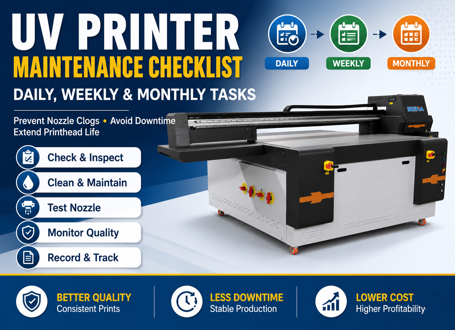
For routine maintenance planning, see our daily, weekly and monthly UV printer maintenance checklist.
자주 묻는 질문
Why Do Lines Disappear When the Pass Count Is Increased?
A higher pass count increases interlacing and overlap between nozzle rows. This can make missing nozzles, step errors or drop-position differences less visible. However, increasing the pass count may only hide the original problem, so the nozzle test and calibration should still be checked.
Why Does Banding Appear Only in Bidirectional Mode?
This usually indicates that ink printed in the two carriage directions is not landing in the same position. Perform bidirectional calibration using the actual material height. Also confirm that the carriage movement and encoder system are clean and stable.
Why Is CMYK Normal but White Ink Has Stripes?
The white nozzle condition, circulation system, dampers, filters and pigment concentration can differ from the CMYK system. Print a white-only nozzle and density test, check circulation and inspect visible white ink lines for bubbles or inconsistent flow.
Can UV Lamp Intensity Cause Visible Bands?
Yes. Uneven curing can create differences in gloss, surface texture or apparent darkness. Print a varnish-only or solid-color test and inspect it from different angles. Do not change lamp power or electrical settings without following the machine’s approved procedure.
Does Replacing the Printhead Always Solve Banding?
No. A new printhead will not correct step calibration, bidirectional alignment, warped materials, unsuitable RIP settings, unstable curing, encoder contamination or mechanical movement errors. Confirm the actual cause before replacing an expensive component.
Why Does the Same File Print Differently on Different Materials?
Materials differ in thickness, flatness, static electricity, coating, surface energy and required printhead height. These differences affect ink-drop placement, adhesion, spreading and curing. Compare the file on a standard flat material to separate machine problems from material-related problems.
Why Do Lines Become Worse During a Long Print?
Banding that increases during production may indicate unstable ink supply, partially blocked filters, air bubbles, temperature changes or nozzle loss. Print another nozzle test immediately after the problem appears and compare it with the test printed before production.
Can a Dirty Encoder Cause Repeated Lines?
Yes. The encoder helps the printer determine carriage or platform position. Contamination can produce incorrect movement information, repeated placement errors or unstable calibration. Clean it only according to the manufacturer’s instructions because the encoder surface can be easily damaged.
결론
The correct way to solve UV printer banding is to identify the pattern before cleaning. Observe the direction, spacing, affected colors, print mode and material conditions. Then print a nozzle test, compare unidirectional printing, increase the pass count by one level, perform alignment and step calibration, and inspect material flatness, ink supply and UV curing.
If the banding remains, send your supplier the nozzle test, full print photo, close-up image, RIP settings and a short operating video. Complete evidence helps the engineer identify the cause before the printhead, dampers or mechanical parts are removed.
Need Help Diagnosing UV Printer Banding?
Send us your nozzle test, print photographs, RIP settings, material information and operating video. Our technical team can help determine whether the problem is related to nozzles, calibration, print settings, materials, ink supply or UV curing.